
Guides · · 6 min read
LOD 200, LOD 300 and Level of Accuracy for a facade model from a scan
What LOD and LOA actually specify for a scan-derived facade model, where the two systems overlap and where they do not, and what an automatic pipeline can honestly deliver at each level today.
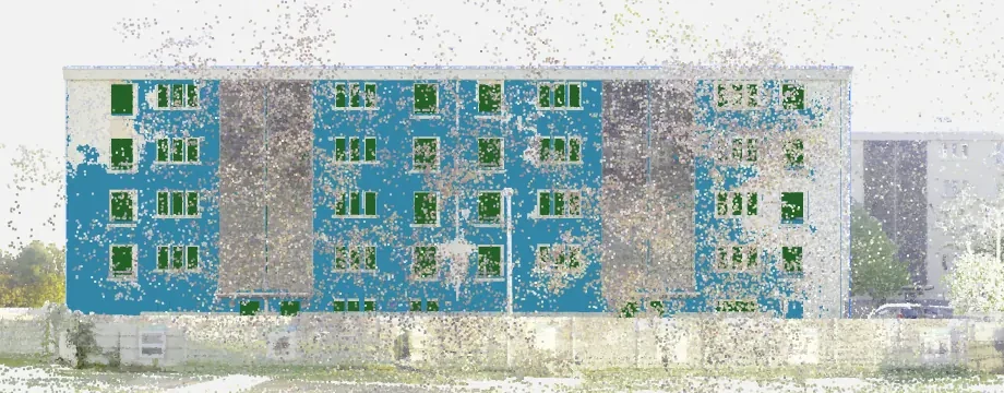
Two systems describe how good a building model is, and they get mixed up in most scan-to-BIM specifications. One is about how much the model says. The other is about how true it is. A facade model from a scan needs both, and an automatic pipeline can only honestly promise one of them. This article separates the two, then places what our pipeline delivers on each scale with the measured numbers.
LOD: how much the element says
Level of Development, in the BIMForum specification used across the AEC industry, describes the reliability of an element’s information for a purpose. It is not a geometric tolerance. The levels that matter for a facade:
- LOD 100: the element exists as a symbol or a mass. A facade is a rectangle.
- LOD 200: a generic element with approximate size, shape and location. A wall with openings roughly where the openings are.
- LOD 300: a specific element with accurate size, shape, location and orientation. A window of this width and height at this position, cut into a wall of this thickness.
- LOD 350: LOD 300 plus interfaces with other systems: how the window meets the wall, the sill, the lintel.
- LOD 400: fabrication detail. The window’s profile, its hardware. Not something a scan provides.
The full family, including LOD 400 and the field-verified LOD 500, is set out in BIM LOD levels explained; this article is about where that scale meets the other one.
The word “accurate” in LOD 300 is where people read a tolerance that is not there. LOD 300 means the element’s geometry is modelled, as opposed to typed in as a nominal placeholder; it does not say how close to reality it is. That is the other system’s job.
LOA: how true the geometry is
Level of Accuracy, from the USIBD (U.S. Institute of Building Documentation) specification, is a tolerance band at a stated confidence. The levels:
| LOA | Tolerance (95 % confidence) | Typical use |
|---|---|---|
| LOA 10 | 5 cm to 15 cm | massing, early planning |
| LOA 20 | 15 mm to 5 cm | design development, most facade surveys |
| LOA 30 | 5 mm to 15 mm | construction documents, fit-out |
| LOA 40 | 1 mm to 5 mm | fabrication |
| LOA 50 | 0 to 1 mm | metrology |
The specification also separates two accuracies: measured (how good the scan is) and represented (how good the model is). A scan at LOA 30 can carry a model at LOA 20, because modelling loses accuracy: the modeller snaps to a nominal 90 cm width, or the software emits every opening at the same depth. Ask which of the two a vendor’s LOA refers to.
Reading a facade specification with both scales
A typical clause, “facade elements to LOD 300, LOA 20”, means: every window and door is a specific, modelled element with its own size and position, and that geometry is within 5 cm of the measured building at 95 % confidence. Turn that into the two questions you can actually check:
- Is every element there and specific? That is recall (how many of the real openings are in the model) and it is LOD 300’s “specific element”: one window per real window, not a repeated typical window.
- Is 95 % of the geometry within 5 cm? That is correctness at 5 cm, on every axis, for at least 95 % of the paired elements.
Those two questions are exactly the two columns we publish, which is not a coincidence: they are the questions any specification eventually asks.
Where an automatic facade pipeline stands on both scales today
Our run of 10 September 2026 on the reference building, scored against the surveyor’s hand-modelled IFC:
| Question | Measured | Reading |
|---|---|---|
| Are the openings there and specific? (windows) | 77 of 96 found, each its own element with its own size | LOD 300 for the 77; the 19 missing are the reviewer’s |
| Position along the facade | median 0.6 cm | LOA 20 territory |
| Height | median 2.0 cm | LOA 20 territory |
| Size (width and height) | median 8 cm | LOA 10 |
| Depth | placeholder, median 20 cm off | not represented yet |
| 95 % within 5 cm on every axis | no: 0 of 77 | not LOA 20 as a whole model |
So the honest description of the automatic proposal is: LOD 300 elements, LOA 20 in the facade plane, LOA 10 in size, and no represented depth. The reviewed model that a person produces from it can be LOA 20 throughout, because the review is where depth and the missing 19 get fixed, and because the in-plane geometry the reviewer starts from is already within tolerance.
What a scan cannot give at any LOD
Some LOD 300 properties are not visible from outside a building, and no pipeline, automatic or manual, gets them from a facade scan:
- Wall thickness. A facade scan sees one face. Thickness comes from an interior scan, a drawing or an assumption; ours emits a nominal one and says so.
- Window construction. Frame material, glazing type, opening direction. Colour hints at material; nothing in the cloud says double or triple glazing.
- Storey levels. The floor is inside the building. From the facade, storey levels are inferred from the rows of openings, and the reference models we score against place them by a drafting convention (a fixed offset above the window row) that the cloud cannot show. Our storey lines are within 5 to 9 cm of the reference on the two buildings measured, and they are inferred, not measured.
A specification that asks for these at LOD 300 from a facade scan alone is asking the modeller to guess; the guess should be labelled.
Verifying LOA on a delivered model
The USIBD specification describes accuracy at 95 % confidence, which is a statistical statement: 95 % of the checked points lie within the band. Verifying it means checking, and checking a facade model has a cheap method and an expensive one.
The expensive method is a check survey: a second, independent measurement of a sample of features with a total station, compared with the model. It is the method the specification assumes, and for a contractual deliverable it is the one that holds up.
The cheap method is the one we use in development: compare the model against another model of the same scan made independently, element by element, on every axis. It does not verify the scan (both models share it) but it verifies the modelling, which is where the accuracy is lost, and it is the method that produced every figure on this page. A client who has one hand-modelled facade can run this on a delivered model in an afternoon, and the platform runs it for them when a reference IFC is attached.
Either way, the check should report the same shape of result: per class, the share of elements within the band on the worst axis, and the median error per axis. A single “LOA 20 achieved” with no table behind it is the same claim as “high accuracy”.
What the IFC file itself says about accuracy
IFC has no field for “this element is within 5 cm”. What it has is identity: every element carries a GUID, and ours are stable across re-exports. The measurement status lives beside the IFC rather than inside it: the run’s element list, delivered as JSON with the same GUIDs, records for each element its confidence, whether it was measured (measured, or unfitted and why) and the review decision with its author and timestamp. Writing those fields into the IFC as a property set is on the roadmap; today a checker joins the two files on the GUID.
For a specification, that suggests one more line: elements carry their measurement status, in the model or in a companion file keyed on the element GUID. It costs nothing and it is the difference between a model you can audit and one you can only re-survey.
Writing the clause
For a facade model derived from a terrestrial scan, a clause that both sides can verify looks like this:
Facade walls, windows, doors and vents to LOD 300. Represented accuracy LOA 20 in the facade plane for the position and size of openings, verified by pairing against a check survey of at least one facade, with recall, precision and the share of paired elements within 5 cm and 10 cm on every axis reported per class. Elements the pipeline could not measure are flagged as such in the deliverable. Wall thickness and storey levels are inferred and labelled inferred.
That clause asks for what can be measured and names what cannot. It also happens to describe what our deliverable contains: the flags, the per-element verdicts and the scoring table are in it because a specification like this needs them.
LOD definitions follow the BIMForum Level of Development Specification; LOA bands follow the USIBD Level of Accuracy Specification, version 3. Measured figures are from the AutoIFC engine’s scoring of 10 September 2026 on the reference building and are kept current on the Accuracy page.
Questions
What is the difference between LOD and LOA?
LOD (Level of Development) says how much information an element carries and how far it may be relied on for design decisions. LOA (Level of Accuracy, from the USIBD specification) says how closely the model's geometry matches the measured building, as a tolerance. A model can be LOD 300 and LOA 20 at the same time.
What LOD is a scan-to-BIM facade model?
Typically LOD 200 for massing and LOD 300 for openings, if the openings are positioned and sized from the scan rather than typed in nominally. Anything about the window's construction (frame, glazing, thermal properties) is beyond what a scan can tell.
What accuracy does LOD 300 require?
LOD itself does not specify a tolerance; that is what LOA is for. In practice, facade specifications pair LOD 300 with LOA 20 or 30, which is 15 mm to 50 mm at 95 % confidence for the represented geometry.