
Accuracy · · 8 min read
Scan-to-BIM accuracy: what the numbers mean, and which ones to ask for
Every vendor says "high accuracy". Here is how to read a scan-to-BIM accuracy claim, the two numbers that must appear together, and a worked example on a real building.
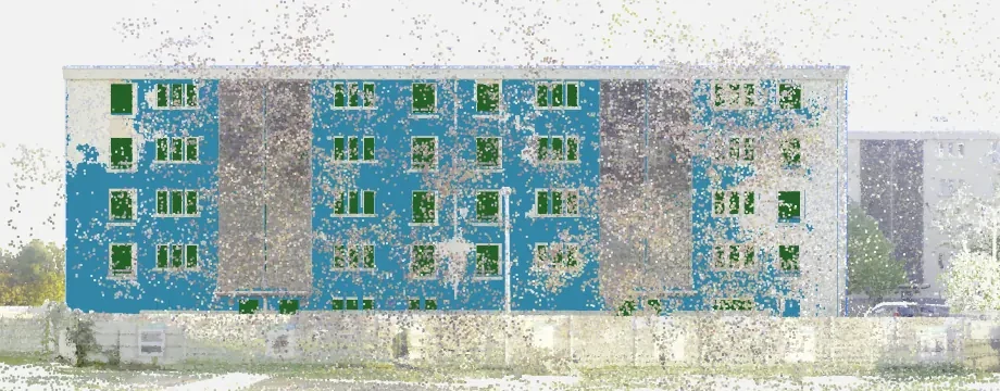
Search for scan-to-BIM software and every result page says the same two words: high accuracy. None of them says high compared to what, measured on which building, by whom. This article is the one we wish had existed when we started: what an accuracy claim about a scan-to-BIM model can mean, why one number is never enough, and how to read the figures we publish for our own product.
Three different things called “accuracy”
When someone says a scan-to-BIM model is accurate, they can mean any of three distinct facts, and the difference matters more than the number.
1. The scan is accurate
A terrestrial laser scanner measures each point to a few millimetres, and a registered multi-station scan of a facade is typically good to 5 to 10 mm overall. This is the accuracy of the input. It caps everything downstream, but it says nothing about the model, because the model is a set of decisions made on top of the points: where does the window start, is this a door or a panel, which of these returns are a railing.
2. The elements were found
The second meaning is completeness: of the 96 windows on the facade, how many appear in the model at all. This is recall. Its twin is precision: of the elements the model contains, how many correspond to something real, as opposed to a tree shadow read as a window. Recall and precision are the numbers most automatic tools quote, when they quote anything, because they are easy to compute and easy to make look good.
3. The elements are in the right place, at the right size
The third meaning is the one a surveyor or an architect actually cares about: is the window that was found correct? Is its sill at the right height, its width the real width, its reveal at the real depth? This is correctness, and it needs a threshold to mean anything. A window whose every dimension is within 5 cm of the reference is correct at 5 cm. One that is 3 cm off horizontally but 20 cm too deep is not correct at 10 cm, because the test applies to the worst axis.
The rule we use: recall and correctness are always shown together. A recall figure without a correctness figure next to it tells you that elements exist, not that they are right. We built that rule into the engine’s scoring code, which refuses to report a recall for a class without the correctness figures for the same class.
How correctness is measured
To measure correctness you need a reference: a model of the same building made independently, ideally by a surveyor from the same scan. Then, element by element:
- Pair each generated element with a reference element of the same class. We pair by overlap in the facade plane (an intersection-over-union of at least 0.20), and for slender elements such as mullions, by centre distance.
- Compare the pair on four measures: position along the facade (u), height (v), size (width and height together), and depth (w).
- Take the worst of the four. If it is within 5 cm, the element is correct at 5 cm; within 10 cm, correct at 10 cm.
Unpaired reference elements are misses (they cost recall). Unpaired generated elements are false positives (they cost precision). Paired elements that fail the threshold are found but wrong, and they are the ones a single “accuracy” percentage hides.
A worked example on a real building
The reference building is a four-storey apartment block with 96 windows, four doors, loggias behind louvred screens and a plinth of vents. It was scanned terrestrially (149.8 million points) and modelled by hand by a surveying company as an IFC. That hand model is our reference. Here is what our pipeline produced on its south facade, scored by the method above, on 10 September 2026.
| Class | Generated | Reference | Paired | Recall | Precision | Correct at 10 cm |
|---|---|---|---|---|---|---|
| Window | 78 | 96 | 77 | 0.80 | 0.99 | 1 of 77 |
| Door | 3 | 4 | 3 | 0.75 | 1.00 | 1 of 3 |
| Wall | 1 | 54 | 1 | 0.02 | 1.00 | 0 of 1 |
| Railing, member, beam, plate, slab | 0 | 160 | 0 | 0 | – | no detector |
Update, 14 September 2026. We stopped publishing a tolerance. Not because ours got worse — it did not — but because we could not defend the figure. Two independent third-party references over one building agree with each other within 10 cm on 2 % of the windows they share; the one pair that could have tested generalisation cannot be rigidly registered; and the estate we can score against a survey is a single typology, so any portfolio number from it would have to be withdrawn the first time a customer scanned something else. We now publish completeness, per-element provenance, and per-axis errors on a named building. The reasoning, in full, is on the Accuracy page. The walk-through below is kept because the way of thinking is right: ask for the ugly column, whoever is selling to you.
Read the window row from left to right. Four out of five windows were found. Almost everything found is a real window. And one of the 77 found windows is correct on every axis at 10 cm. That last cell is the honest one, and it is the one nobody publishes.
Why the last column is so low, and why it is not the disaster it looks like
The median errors explain it:
| Measure | Median error |
|---|---|
| Position along the facade (u) | 0.6 cm |
| Height (v) | 2.0 cm |
| Size | 8 cm |
| Depth (w) | 20 cm |
Three of the four axes are good, and two are excellent: 0.6 cm along the wall and 2.0 cm in height would satisfy any facade survey. The fourth is a constant: this version of the pipeline emits every opening with a placeholder depth, because the depth fitter is not written yet. So every window fails the worst-axis test on the same axis for the same reason. When depth is fitted from the scan, which is the next change to the engine, that column moves, and the size column with it. Until then, the table says so.
That is exactly what a correctness figure is for. A vendor quoting “80 % accuracy” on this facade would be telling the truth about recall and hiding the depth. A vendor quoting “windows within 2 cm” would be telling the truth about height and hiding the depth. Only the table tells you what you are getting.
The reference is not the truth either
A scoring table only makes sense if you know how good the reference is. The surveyor’s IFC we score against was modelled by hand from the same scan, by a company that does this for a living, and it is the best independent model of the building we have. It is still a model, with its own conventions, and two of them show up in the table.
First, the reference window sits above the hole. An IfcWindow in the reference bears about 21 mm above the bottom of the IfcOpeningElement it fills, on both buildings we measured, while its other three edges sit on the void exactly. So a pipeline that measures the void’s bottom edge perfectly will still read 21 mm “low” against the reference. We know that offset because we measured it; a vendor who did not would report an error that is not theirs.
Second, the reference wall is 54 pieces. The surveyor splits the wall by storey and by pier, following the architect’s levels, which are inside the building and invisible to a facade scan. Our pipeline emits one wall per facade. Scored naively that is a recall of 0.02 on walls; scored on area overlap it is a single wall covering the same surface. Both figures are true, and only one of them means anything, which is why the class table needs a caption.
The lesson is not that references are bad. It is that a claim of “3 cm accuracy” with no reference named is unfalsifiable, and a claim with a reference named comes with that reference’s conventions, which an honest table explains.
Reading accuracy claims in the wild
Here are the shapes accuracy claims take on vendor pages and in tender responses, and what each one actually tells you.
| The claim | What it measures | What it hides |
|---|---|---|
| “Millimetre accuracy” | The scanner | Everything the modelling did to it |
| “95 % accuracy” | Usually recall, sometimes per-point segmentation | Whether the found elements are the right size and depth |
| “LOD 300 compliant” | The elements are specific, not typical | No tolerance at all; LOD is not an accuracy |
| “Within 2 cm” | One axis, often position in the plane | The other axes; ask for the worst-axis figure |
| “Validated on 50 buildings” | The tool ran on 50 buildings | Against what reference, with what result |
| Recall, precision and correctness at 5 / 10 cm per class, on a named building with a named reference | What you will get | Nothing; that is the point |
None of the first five is a lie. Each is a true statement about one thing, offered where you expected a statement about another. The last row is what to ask for, and if a vendor cannot produce it, the honest answer is that they have not measured their own output.
What a specification should ask for
If you write or receive scan-to-BIM specifications, the accuracy clause is usually a Level of Accuracy from the USIBD guide or a tolerance in millimetres borrowed from the scan. Both describe the input. For the model itself, ask for four things:
- A named test building with an independent reference model, and the class list of that reference. “Accurate” on a plain box facade means little.
- Recall and precision per class. Windows and walls behave differently; a global figure hides the class that failed.
- A correctness threshold on the worst axis, 5 cm and 10 cm, per class, with the median error on each axis so you can see where the threshold fails.
- The abstentions. A pipeline that guesses where it cannot measure will score worse and look better. Ask which elements were marked as unmeasured, and why.
How the same building scores in other hands
That surveyed estate has been modelled more than once. On a sister building of the same estate (85.7 m long, 188 windows), the engine finds 0.99 of the reference windows at a precision of 0.94, and covers 96 % of the wall surface. What it will not tell you is a tolerance, for the reasons in the update above
What you can do with a model that is “found but not yet correct”
A model that finds 80 % of the openings and places them within 2 cm in the plane is not a finished deliverable, and it is not useless either. It is a proposal that a person can review in minutes instead of drawing in days: every element is where it should be on the elevation, and the reviewer’s job is to accept it, reject the tree shadow, fix the depth on the ones that matter, and add the missing fifth. That review step is why we publish the ugly column: the reviewer needs to know where to look, and “80 % accurate” would send them looking in the wrong place.
The walked-through figures are the engine’s own scoring run of 10 September 2026 on the reference building against the surveyor’s IFC; the update and the sister building are the engine of 13 September 2026. They are updated on the Accuracy page when the engine changes.
Questions
What accuracy should I expect from scan-to-BIM?
It depends on what is measured. On a scanned facade, an automatic pipeline can place window edges within a few centimetres along the wall and in height, but depth and small members are harder. Ask for recall, precision and a correctness threshold on a named building, not a single percentage.
Is recall the same as accuracy?
No. Recall says how many of the real elements were found at all. It says nothing about whether they have the right size or position. A model can find every window and place them all 20 cm too deep.
What is a good correctness threshold for a facade model?
10 cm on every axis matches what most LOD 300 specifications imply for openings; 5 cm is a stricter target that hand modelling from a good scan reaches on position but rarely on every axis.